 China Truck Plant
 Aircraft refueling truck
 Dump truck
 Truck-mounted crane transport vehicle
 cement mixer truck
 cargo trucks
 fuel truck
 garbage truck
 Sewage suction truck
 Aerial work vehicle
 Car carrier
 military vehicles
 Other models
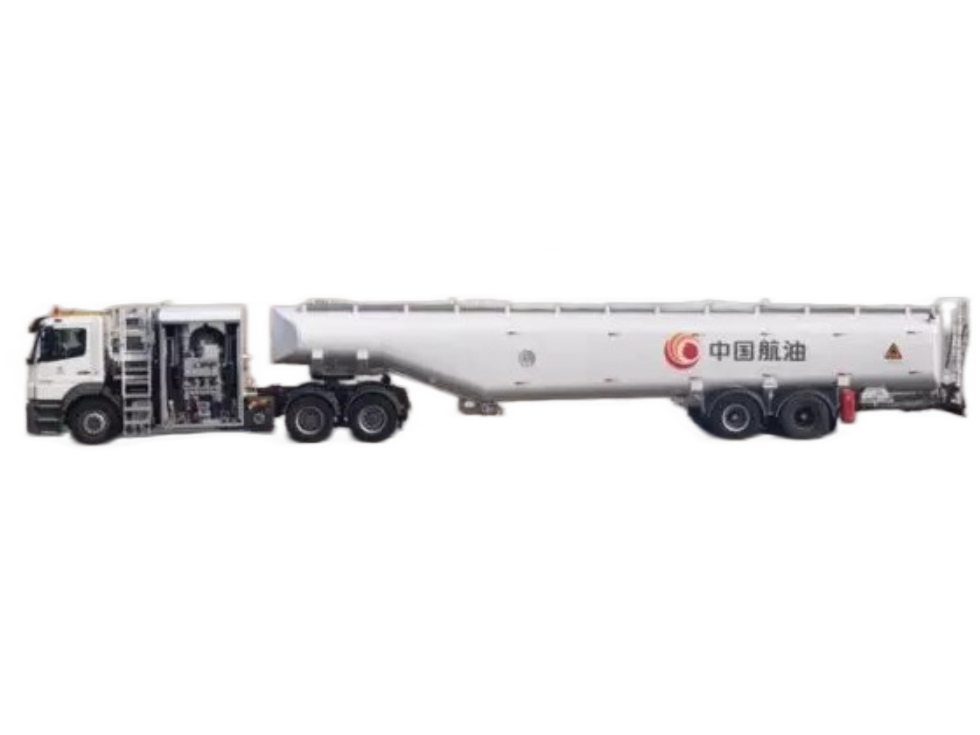
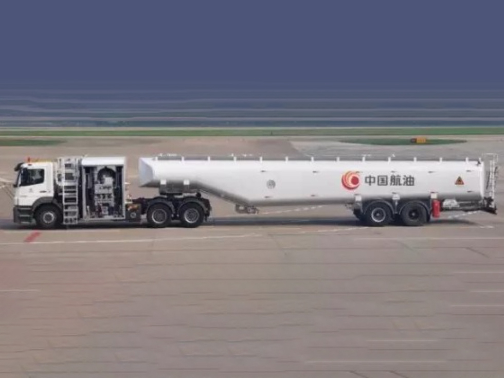
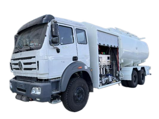
45 cubic meter civil aviation semi-trailer tanker refueling truck
CL9245GJY-BJ Civil Aviation Aircraft Tank Refueling Truck Configuration 1. Overview The CL9245GJY-BJ semi-trailer aircraft refueling truck (hereinafter referred to as "refueling truck") features large capacity, good mobility, and full functionality. It is mainly used within airports to provide pressurized refueling for aircraft equipped with pressurized refueling interfaces.
Sufficient stock available
A large fleet of specialized vehicles is available for fast delivery!
Delivery time
In-stock vehicles can be delivered within 1-3 days; customized models will be delivered according to the contract timeframe!
CL9245GJY-BJType of civil aircraft tanker refueling truck configuration
1. Overview
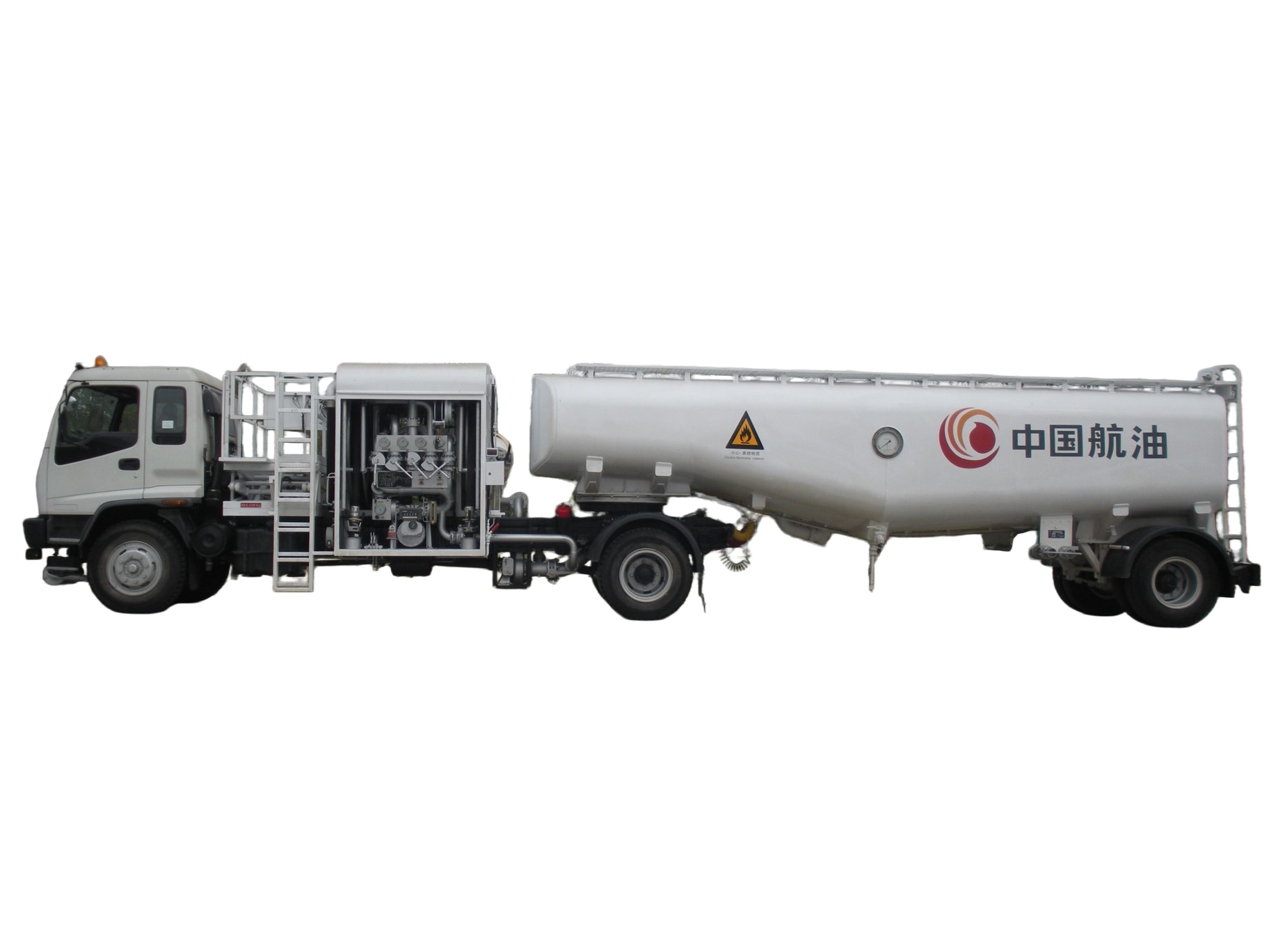
CL9245GJY-BJSemi-trailer aircraft refueling truck (hereinafter referred to as...)The "refueling truck" is characterized by its large capacity, good mobility, and full functionality. It is mainly used in airports to perform pressurized refueling and oil extraction for aircraft equipped with pressurized refueling interfaces.
2.shape
|

3. Functions and main parameters
3.1 Function
① Oil reel (single or double tube)
② Platform refueling (single or double refueling)
③ Oil extraction using a reel (single tube)
④ Platform oil extraction (single or double tube)
Overall vehicle dimensions | 18800*2500*3800 (for reference) | |
volume | 45000L (reference) | |
Fuel flowL/min | single tube reel | 1200 (Reference) |
Platform dual-pipe | 2400 (Reference) | |
Oil pumping flow rateL/min | single tube reel | 600 (Reference) |
Platform dual-pipe | 1200 (Reference) | |
Fuel nozzle filler volumeL/min | DN25/DN38/DN50 | 200/350/500 (Reference) |
Oil volume | 1500L/min (reference) | |
⑤ Oil filling
3.2 Main parameters
4. oil tank
4.1 Oil Tank Materials
Tank body, end caps, and protective measureswaveMaterials such as boards are5182Aluminum alloy plate, bracket isCombination of aluminum alloy and carbon steel。
4.2 oil tank structure
①The oil tank is welded from a cylindrical body and a bracket, and adopts a variable cross-section structure. A sedimentation tank, a drain outlet, and a drain valve are installed at the lowest point of the bottom of the oil tank.
②Each piece of protectionwaveThe plate has a manhole to allow access to the oil tank for cleaning and maintenance.
③A float-type level gauge is installed on the left side of the oil tank to monitor the oil level.
④A manhole is made on the top of the oil tank, and a corresponding manhole cover is installed. The manhole cover is equipped with a flame arrestor vent valve and an observation port with emergency venting function.
⑤The oil drain port at the bottom of the oil tank is connected to the pneumatically controlled bottom valve of the oil pump system, and an anti-vortex device is installed at the oil drain port.
⑥The oil inlet of the oil tank is connected to the bottom oil loading device, and a baffle plate is installed inside to prevent splashing.
⑦The oil tank is also equipped with high and low level switches to control the amount of fuel.
⑧The top of the oil tank is equipped with a pedestrian walkway, and the rear is equipped with a non-slip ladder.
5. trailer chassis
The trailer chassis consists of axles, suspension, and air braking system.
5.1 air braking system
①Emergency relay valve
In a dual-circuit trailer braking system, the trailer's braking is controlled by the control pressure from the tractor.
② relay valve
It can quickly charge and vent the brake chamber.
5.2 axle and suspension
① It adopts Guangdong Fuhua extended axle and reverse-mounted suspension system. Load capacity is...18The load capacity is 1 ton, which meets the load requirements of this vehicle model.
② Install a hand crank on the traileroutriggerFor use in maintenance or transportation by vehicle or shipstopVehicle brakes.
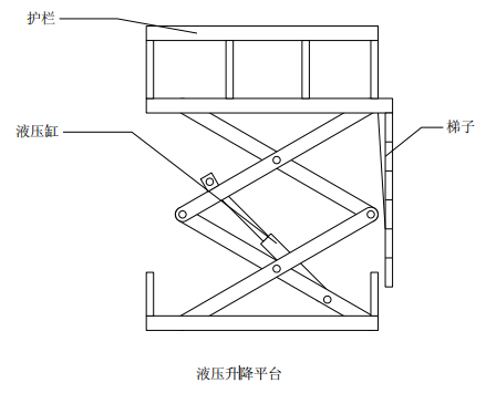
6. Lifting Platform
Used to elevate personnel to a suitable height for refueling and oil extraction operations.
6.1 Main parameters
① External dimensions:
lGuardrail Length, Width, and Height: 2200×1000×1000mm
lLifting height((Platform floor distance from ground)reference:lowest:1650mm;Highest:4200mm
② Rated load:150kg
③ Maximum load:300kg;
6.2 structure
 column
7. Control room
alsoEquipment compartment,CanOpenOr the roller shutter door is closed.Frame structure, containingElectronic controlSystem, hydraulic system, pneumatic control systemDisplay instruments, etc.Components. To reduce wear caused by friction between the hose reel and the door frame during winding and unwinding,reelRollers are installed on the frame.
8. Oil pump system
The oil pumping system is the functional execution system of this product. Under the logic control of the pneumatic control system, it can complete refueling, oil pumping, and oil filling operations for external equipment to supply oil to the vehicle's fuel tank. This system mainly consists of a centrifugal pump, filter separator, flow meter, and pressure control valve.(PCV)It consists of a venturi tube, a pneumatically controlled bottom valve, a pressure filling nozzle, a filling hose, a connector valve, a bottom filling device, and a sampling system.
8.1 Main functions
① Oil reel (single or double tube)
② Platform refueling (single or double refueling)
③ Oil extraction using a reel (single tube)
④ Platform oil extraction (single or double tube)
⑤ Oil filling
8.2 Main technical performance indicators
① Refueling maximum flow
lMaximum flow rate for single-pipe (reel) refueling.L/min: 1200
lDual-pipe (platform) refueling maximum flow rateL/min: 2400
② Maximum oil extraction flow rate
lMaximum flow rate for single-tube oil extraction from a hose reel.L/min: 600
lMaximum flow rate for single-tube oil extraction on the platformL/min: 600
lThe platform's dual-tube oil pumping maximum flow rateL/min: 1200
③ Maximum oil loading flow rateL/min:1500(Single tube)/2500(Double tube)
④ Flow meter accuracy: ±0.2%
⑤ The performance indicators of the filter separator meet the requirementsAPI1581。
⑥ Dual pressure control for refueling (online and terminal), with online pressure control.0.35MPaAdjustable.
⑦ 1 or 2Root reel hose, diameter63mm,long20m。
⑧ 2Root platform hose, diameter63mm,long3.5m。
8.3 Main components
8.3.1 pump
SelectDomesticBrand centrifugal pump, maximum flow rate3000Lift/minute, normal operating pressure is 0.40—0.6Between 0 MPa.
1) Rated speed,rpm: 1190
2) Rated flow rateL/min:2500
3) Yangchengm: 120
4) Power (fuel density:830 kg/m3),kw: 90
8.3.2 Filter separator
Selected filter separators from well-known domestic and international brandsand meet the following requirements:API1581The fifth-generation filter separator has the following parameters:
① flow:2500L/min。
②Work pressure1.0 MPa.
③Install the manufacturer's original automatic air vent valve and safety valve with check valve, install a sight glass, and connect it to the large tank via an independent pipeline.
④Contains0-0.15Megapascal piston differential pressure gauge.
⑤Both the inlet and outlet of the filter have Meilipu test points, and there are dedicated valves controlling the test points.
⑥Filter/Separator with sewage discharge device.
8.3.3 Flow meter
The flow meter used on the refueling truck should be a well-known domestic brand and meet the following requirements:
(1) Flow rangeL/min:250~2500 ;The accuracy class of the flow meter is not lower thanLevel 0.2, using mechanical or electronic reading methods, batch display can return to zero, but cumulative display cannot.;It also provides an instantaneous flow rate indicator.
(2) During the oil extraction process, the count is recorded normally and accumulated.
(3) Working pressure 1.0 MPa.
(4) The flow meter is easy to install, calibrate, and replace.
8.3.4 Pressure control valve(PCV)
Using Dedman(DEADMAN)In-pipe pressure control valve
(1) maximumOfficialpressure,MPa(bar):1.0
(2) Maximum flow rateL/min:2400
(3) pressureAdjustment range0.14~0.049MPa
(4) Dedman Control
Opening times:10 Closure time,s:5
9. Hydraulic system
The hydraulic system completes the winding, unwinding, and braking of the hose, as well as the lifting and lowering of the platform.
9.1 Reel control
This function hydraulically controls the braking and rotation of the hose reel, thereby ensuring that the hose reel performs the following... Three operating conditions:
(1) Reel brake
(2) hose unfolding
(3) Hose winding
The hydraulic system ensures that the two reels can work independently without interfering with each other.1minOne inside 63mm×20mAll the refueling hoses are rolled back, and the winding speed is adjustable within a certain range.
9.2 Platform lifting
This function uses hydraulics to raise or lower the platform to provide a suitable operating position.
Hydraulic systems can15The platform can be raised or lowered within seconds, and the lifting speed is adjustable within a certain range.
To ensure safety, the hydraulic system is equipped with the following facilities.
(1) The lifting platform is equipped with an emergency shutdown switch to shut off the engine in case of hydraulic system failure.,Cut off hydraulic power.
(2) Equipment compartmentTop equipped withcontrolThe valve can be operated from the ground to lower the platform.
10. pneumatic control system
The pneumatic control system is the control system that enables the refueling truck to complete various operations. Through specific logic control, it ensures that the pumping system performs its normal functions. The system's pneumatic supply is provided by the vehicle's chassis.gas storage tankReceived.
10.1 Function
(1) add/Oil pumping operation
(2) Platform lifting
(3) The engine automatically slows down to idle speed when the operation is finished.
(4) Dedman and Beyond
(5) Oil tank high and low level control
(6) Engine emergency shutdown
(7) Operating brake interlocking and overrunning. Provides signal displays for all interlocking points for monitoring and troubleshooting. Interlocking The affected areas include the following:
a)PTO engagement
b)Platform rise
c)The fuel filler connector was not reset.
d)Oil filler bumper not reset
and) Static grounding clamp not reset
f)movable guardrailNot reset
10.2 An electronic interlocking system, an electronic Dedemann system, or a time-controlled Dedemann system can be selected according to user requirements.
11. Electrical system
It consists of the vehicle chassis electrical system and the retrofitted electrical system. The retrofitted electrical system provides Deadman control, It includes functions such as lighting, status display, and signal indication. This ensures reliable connections between electrical components and wiring. For safety and reliability, the lighting signal lights are all double-wired, with the ground wire located at the lower front of the cab.
11.1 illumination
To facilitate nighttime operation, explosion-proof lights are installed inside the front cabinet and on the platform.
11.2 Status display
The cab is equipped with a power take-off indicator light and safety interlock indicator lights for each connector, allowing for quick understanding of the vehicle's status. The state is as follows:
lInterlock indicator light (yellow)
lInterlocking overrun indicator light (red)
11.3 Signal indication
A yellow signal flasher (warning light) is installed on the top of the cab, and the rear of the trailer is equipped with turn signals, taillights, brake lights and license plate lights, which serve as identification signals for vehicles traveling within the airport.
11.4 Electric control Dedemann
The advantages of the electronically controlled Dedemann are that it is not afraid of freezing at low temperatures, making it suitable for use in northern regions, while also providing a safer time control function.
12. Other safety measures
In addition to the dedicated safety devices for each system, the vehicle also has the following additional safety measures:
(1) Install an electrostatic grounding reel; the total length of the grounding wire is [length missing].25mThe reel allows the grounding wire to remain in either position when it is unrolled. Location, the end of the grounding wire is equipped with a flexible..."Alligator clip".
(2) The bottom of the oil tank is equipped with anti-static mopping tape.
(3) The engine exhaust pipe muffler is equipped with a flame suppressor and is modified to be located at the front of the cab, with the exhaust outlet avoiding the refueling operation area.
(4) One is installed on each side of the refueling truck at an easy-to-access location.8kgDry powder fire extinguishers.
Product customization
If you cannot find a suitable product, you can also leave us a message and write down the product configuration you need. We will reply to you within 1-2 business days after receiving your message!